Views: 0 Author: Site Editor Publish Time: 2026-08-25 Origin: Site
Premature castable lining failure directly impacts operational uptime and maintenance budgets across industrial facilities. Improper anchor layout stands as a primary culprit for thermal spalling and mechanical collapse. Engineers face a constant challenge balancing anchor density on the steel shell. Too few anchors lead to insufficient support, causing eventual lining detachment and catastrophic drop-outs. Too many anchors create excessive thermal transfer, internal stress, and localized cracking around the metal tines. We must move beyond generic rules of thumb. An evidence-based, calculated approach is necessary for monolithic linings. There is no single universal standard for every vessel. Determining proper layout, pattern design, and embedment depth depends entirely on specific operational parameters, thermal cycling, and the unique mechanical properties of the chosen refractory material.
Standard baseline spacing for vertical walls typically ranges from 250–350mm (2–4 anchors per square foot), but spacing tables should be used as a guide only, requiring adjustment for specific mechanical and thermal loads.
Overhead and roof applications demand a 20–30% reduction in spacing distance to counteract gravitational shear forces on the castable.
High-stress zones, including edges, corners, and penetrations, require up to 50% closer spacing (e.g., 200–250mm) to maintain structural integrity.
Anchor metallurgy, lining thickness, thermal cycling profiles, and the specific type of unit being lined (e.g., static furnace vs. rotary kiln) are critical evaluation dimensions that dictate final pattern design and density.
Table of Contents
Carbon steel shells, stainless steel anchors, and alumina castables all expand at vastly different rates when exposed to operating temperatures. Carbon steel expands significantly more than ceramic refractory materials. Stainless steel anchors expand even faster than the carbon steel shell. This mismatch creates massive shear stress at the anchor-castable interface. When you fire the vessel, the steel casing grows outward and pulls the welded anchors with it. The castable lining tries to remain static. Proper spacing dictates how this mechanical stress distributes across the monolithic structure during heat-up and cool-down cycles. The anchor system acts as a flexible skeleton. It must hold the refractory against the shell while accommodating these differing expansion rates without rupturing the castable.
Getting the density wrong guarantees premature failure on the unit. You must analyze both extremes to understand the mechanical risks involved on the job site.
Under-spacing (Too far apart): Insufficient holding power leaves large sections of the castable unsupported. The lining begins to bulge away from the steel casing as thermal expansion pushes the material inward. Gravity and thermal movement eventually cause massive sections to detach. This catastrophic failure forces immediate shutdowns, exposes the steel shell to direct flame impingement, and requires extensive demolition and rework.
Over-spacing (Too close together): Packing anchors tightly creates a different set of severe problems. Dense anchor populations act as thermal bridges. They transfer excessive heat directly from the hot face to the steel casing, risking structural warping and paint failure. Overlapping expansion zones from tightly packed anchors cause the refractory to crack. The metal expands, pushing against the rigid castable. When anchors sit too close, these expansion zones collide, crushing the surrounding refractory and causing localized spalling across the entire wall.
Industry guidelines provide a starting point for static vertical walls. Standard refractory anchor spacing typically falls between 250mm and 350mm. This translates to roughly two to four anchors per square foot of surface area. This baseline assumes standard operating conditions inside static equipment like boilers or reheat furnaces. It also assumes a uniform lining thickness and a relatively stable thermal environment. You cannot blindly apply this baseline to every project. It serves only as a foundational metric. Engineers must adjust these numbers based on specific thermal loads and mechanical stresses present in the actual operating environment.
To determine the correct baseline for a specific vertical wall, follow these field assessment steps:
Measure the total surface area of the vertical steel casing.
Identify all penetrations, access doors, and burner blocks that interrupt the continuous wall.
Calculate the dead weight of the proposed castable volume based on the material's bulk density.
Determine the maximum continuous operating temperature at the hot face to select the proper anchor alloy.
Map out the expansion joint locations before marking the anchor grid.
Overhead installations completely change the mechanical dynamics of the lining system. Gravity constantly pulls the monolithic lining downward, creating severe shear forces on the anchor attachment points. To counteract this dead weight, roof applications require a 20% to 30% reduction in spacing distance. Tighter density ensures the load distributes evenly across more support points. If you use vertical wall spacing on a roof, the weight per anchor exceeds the yield strength of the steel at high temperatures. The anchors will stretch, deform, and eventually fail, dropping the entire roof lining into the vessel and destroying the equipment below.
Certain areas inside a furnace or vessel endure extreme punishment. Doors, burner blocks, corners, and transition zones face concentrated thermal shock. They also experience high mechanical abrasion and turbulent gas flows. These high-stress zones require up to 50% closer spacing. You must reduce the distance to 200mm or even 150mm depending on the severity of the conditions. Tighter density maintains structural integrity where the castable is most vulnerable to cracking and erosion. Around penetrations, the refractory lacks continuous support, making robust anchoring absolutely critical to prevent edge spalling.
Application Area | Standard Spacing Range | Adjustment Factor | Field Notes |
|---|---|---|---|
Standard Vertical Walls | 250mm - 350mm | Baseline (2-4 per sq ft) | Assumes static loads and uniform thickness. |
Roofs and Overhead | 175mm - 280mm | 20% - 30% Reduction | Requires heavier gauge wire to resist sagging. |
High-Stress Zones & Edges | 150mm - 250mm | Up to 50% Reduction | Apply around all burner blocks and access doors. |
The specific type of unit being lined drastically alters your requirements. Static boilers and traditional furnaces exert predictable, steady loads on the lining. Rotary kilns, cyclones, and moving vessels introduce dynamic forces. Vibration, rotational shear, and constant movement require much tighter refractory anchor spacing. You must also specify heavier anchor gauges to handle these dynamic loads. A rotary kiln subjects the lining to alternating compression and tension with every rotation. The castable hangs from the roof on one half of the rotation and sits on the floor on the other. The anchoring system must be robust enough to hold the castable tight against the shell despite this relentless mechanical fatigue.
Anchor density directly correlates with lining thickness. Thicker linings increase the dead load per anchor. You must adjust either the anchor diameter or the spacing density to support this extra mass. The rule of embedment dictates that anchors should penetrate 66% to 75% (roughly two-thirds to three-quarters) of the total castable lining thickness. If you have a 200mm thick lining, the anchor should measure between 130mm and 150mm long. If the anchor is too short, it fails to grip the bulk of the material, leading to surface spalling. If the anchor is too long, the tip sits too close to the hot face. It will oxidize rapidly, melt, and destroy the surrounding refractory.
Continuous high-temperature operations require different anchoring strategies than frequent thermal cycling. Batch processes subject the lining to rapid heat-up and cool-down phases. This thermal shock causes severe anchor fatigue. The metal expands and contracts repeatedly, weakening the weld and the stud itself. Highly cyclical environments demand tighter spacing to distribute these intense stresses. In continuous operations, the primary concern shifts to creep resistance and oxidation at sustained high temperatures, making anchor metallurgy just as important as the physical layout.
The bulk density of the refractory material impacts the load-bearing requirements. Dense, low-cement castables weigh significantly more than lightweight insulating castables. Heavy materials exert more gravitational pull and shear force on the anchors. You must decrease the distance between anchors when installing dense castables to support the added weight safely. Conversely, lightweight insulating castables impose less mechanical strain, allowing for slightly wider spacing. However, insulating castables often lack high structural strength, so the anchors must still provide adequate skeletal support to prevent the material from crumbling under its own weight.
Castable Type | Typical Bulk Density (kg/m³) | Anchor Load Impact |
|---|---|---|
Lightweight Insulating | 800 - 1,300 | Low dead weight; wider spacing acceptable. |
Conventional Fireclay | 1,900 - 2,200 | Moderate dead weight; standard baseline applies. |
Dense Low-Cement | 2,400 - 2,800 | High dead weight; requires tighter spacing and thicker studs. |
Grid layout matters just as much as density. A straight square grid aligns anchors in continuous rows and columns. This creates straight, uninterrupted paths for stress to travel. If a crack forms, it will propagate rapidly along these linear planes, splitting the wall in half. A staggered or diamond pattern offers significant structural benefits. It disrupts continuous cleavage planes. Staggered patterns distribute mechanical and thermal stress much more evenly across the steel shell. This layout forces cracks to arrest or change direction, absorbing the energy and preventing massive, localized lining failures.
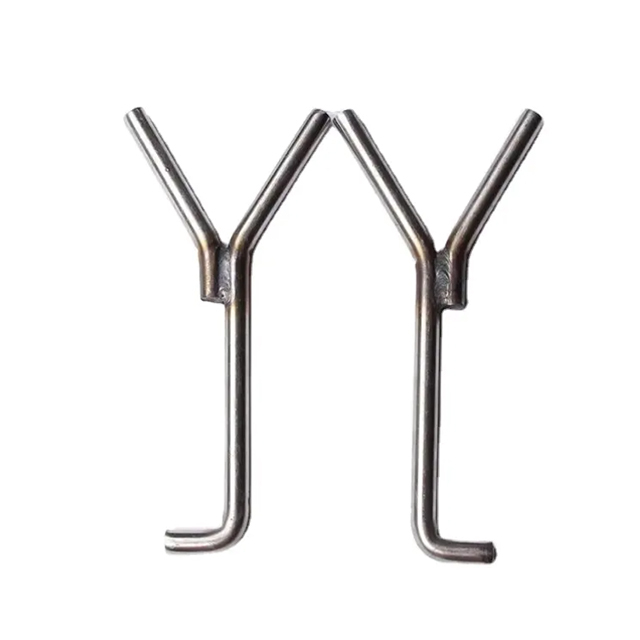
The physical orientation of the anchor tines plays a major role in lining survival. For V-type or Y-type anchors, you must orient the tines perpendicular to the primary direction of thermal expansion or material flow. If the primary expansion is vertical, orient the legs horizontally. If you align the tines parallel to the expansion forces, you create continuous cleavage planes. The legs will push against each other and split the castable right down the middle of the anchor lines. Random or incorrect orientation guarantees linear cracking. Installers must carefully align every single anchor to ensure the tines actively resist the dominant stress vectors.
Expansion joints allow the monolithic lining to grow without buckling. Anchors must be positioned carefully relative to these joints. Keep anchors a specific distance away from the joint edge, typically 50mm to 75mm. If anchors sit too close, they restrict the castable's ability to move, defeating the purpose of the joint. The refractory will bind against the anchor, causing severe edge spalling. Engineers must map out expansion joints first, then design the anchor pattern around them, ensuring unrestricted movement while maintaining adequate support near the gaps.
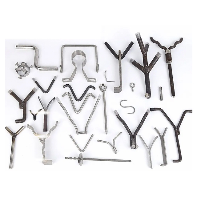
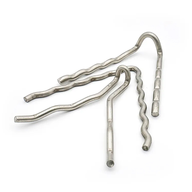
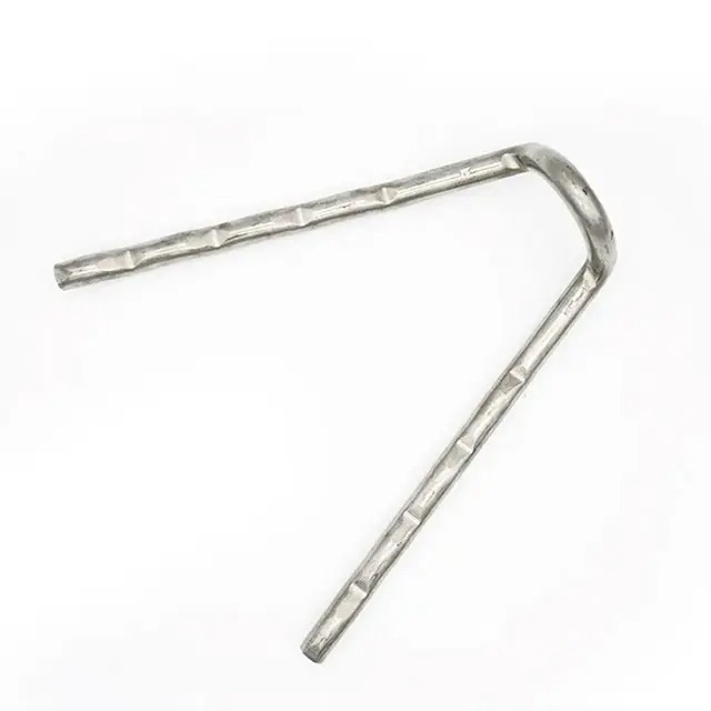
Standard metallic anchors dominate most installations. The mechanical properties and metallurgy of these anchors dictate their maximum spacing limits. Common alloys include 304 stainless steel for temperatures up to 800°C, 310 stainless steel up to 1000°C, and high-nickel Inconel 601 for extreme heat. Yield strength drops significantly at elevated temperatures. You must evaluate the trade-offs between anchor diameter and spacing density. A thicker anchor offers higher yield strength, allowing for slightly wider spacing. However, thicker anchors also conduct more heat to the casing and exert more expansion force on the surrounding refractory.
When operating temperatures exceed 1100°C (2000°F) or involve highly corrosive atmospheres, metallic anchors fail rapidly. They lose their yield strength and turn soft. You must transition to ceramic anchors. Ceramic anchors possess a much larger physical profile and entirely different expansion characteristics than steel studs. They do not expand significantly under heat. This requires specific spacing calculations and specialized metallic C-clips welded to the shell. The ceramic block slots into the clip. Ceramic anchors provide excellent holding power in extreme heat but require precise installation to prevent the heavy ceramic blocks from cracking during the initial castable pour.
Very thin castable linings or areas subject to severe mechanical abrasion require a different approach. Fluid catalytic cracking (FCC) cyclones and fluid bed combustors often use hexmesh instead of discrete anchor studs. Hexmesh acts as a continuous cellular grid welded directly to the casing. It fundamentally changes the approach to refractory anchoring. Instead of individual points of support, hexmesh divides the castable into thousands of small, independent hexagonal cells. This prevents widespread cracking and offers unparalleled erosion resistance. However, it requires intensive welding and precise rolling to match the vessel contours.
Perfect spacing calculations mean nothing if the weld to the casing fails. The anchor attachment point is the weakest link in the entire system. Implement strict inspection protocols for weld integrity. Surface preparation is non-negotiable. Grinding the steel shell to bare white metal removes scale, rust, and old refractory. Welders must use the correct amperage and consumable rod for the specific anchor metallurgy. Conduct hammer tests on a percentage of installed anchors to verify weld penetration and strength before pouring any castable. If an anchor snaps off during a hammer test, the welding procedure must be recalibrated immediately.
Metallic anchors expand significantly more than the surrounding castable during the initial heat-up. You must provide an expansion allowance. Install plastic caps or wrap the anchor tips with heavy tape before pouring the refractory. These materials burn out at low temperatures during the dry-out phase. This leaves a small void at the anchor tip, allowing the metal to expand freely without crushing the rigid castable. Failure to accommodate this expansion leads to immediate, localized spalling right at the anchor points, regardless of how perfect the spacing might be.
Never pour castable without a formal audit of the anchor installation. Outline clear steps for verification on the job site. Measure the distance between anchors to ensure compliance with the engineered pattern. Check the alignment of the tines to verify they sit perpendicular to the stress vectors. Measure the embedment depth to confirm the anchors will sit 66% to 75% inside the finished lining. Documenting these checks prevents catastrophic failures and ensures the physical installation matches the engineering design perfectly.
Audit your current vessel conditions and identify areas of thermal fatigue or mechanical abrasion before planning the next reline.
Request a technical review of your existing anchor layout from a qualified refractory engineer to ensure it meets the demands of your specific operating environment.
Submit your specific operational parameters, including thermal cycling and chemical exposure, to obtain a custom spacing specification before your next turnaround.
Standardize your site inspection protocols to include mandatory hammer testing and embedment depth verification prior to any castable pouring.
For industrial facilities relying on high-temperature equipment, selecting reliable refractory components and working with an experienced supplier can significantly improve lining performance and reduce maintenance risks. Jiangsu Leader Special Steel Products Co., Ltd. specializes in refractory anchors and special steel products, providing customized solutions with professional manufacturing capabilities and technical experience to support demanding applications in furnaces, kilns, and other thermal processing equipment.
A: The general baseline for standard vertical walls is 250–350mm, which equates to roughly 2 to 4 anchors per square foot. However, there is no single universal standard. This baseline requires adjustments for roofs, edges, penetrations, and specific dynamic equipment to ensure adequate holding power and prevent thermal failure.
A: Refractory anchors should typically penetrate 66% to 75% (two-thirds to three-quarters) of the total castable lining thickness. This embedment depth ensures sufficient holding power within the bulk of the material while keeping the anchor tip far enough away from the hot face to prevent rapid oxidation and melting.
A: Roof and overhead applications endure constant gravitational pull. This dead weight creates severe shear forces on the monolithic lining. To counteract these forces and prevent the castable from detaching, overhead installations require a 20% to 30% tighter spacing density to distribute the massive load across more support points.
A: Dynamic equipment like rotary kilns introduces severe mechanical stress, vibration, and rotational shear. Unlike static furnaces, moving vessels subject the lining to constant fatigue. This requires much tighter spacing, heavier anchor gauges, and highly engineered staggered patterns to prevent mechanical failure and keep the castable locked against the shell.
A: Thicker refractory linings weigh significantly more, increasing the dead load that each individual anchor must support. To handle this added mass safely, engineers must either increase the anchor diameter for higher yield strength or decrease the spacing distance to distribute the heavy load across a denser grid of anchors.
A: A staggered or diamond pattern is highly recommended over a straight square grid. Staggered patterns prevent continuous crack propagation by disrupting linear cleavage planes. This layout distributes mechanical and thermal stress much more evenly across the steel shell, reducing the risk of massive, localized lining failures.
A: Yes. Ceramic anchors possess a much larger physical profile and do not expand under heat like steel studs. Because they are used in extreme temperatures (above 1100°C) and carry heavier loads, they require specific spacing calculations and specialized metallic C-clips for attachment, differing entirely from standard metallic anchor grids.